Table of Contents
2016-02-01 - esp8266
 in last months few ppl asked me about esp8266 wifi module. i finally made some digging and bought one for tests. the nice thing is it costs under 5EUR! :)
how to run it? of course all the pieces of information “are out there”. the problem is they are scattered and sometimes contradicting. this makes it a bit more difficult to start. if you are attempting to make it work, this post would be a good place to start.
some basics
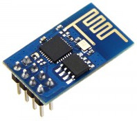
first of all esp8266 is NOT a board - it's a µC, that has wifi module build in. many dev boards are named “esp8266”, this introducing a bit confusion. most ppl, for their hobby designs will prefer dev boards, as they are small and easy to solder (goldpins or similar).
another thing is the SW. dev boards usually consist of 2 IC elements: esp8266 itself and external memory for program (0.5MB is a popular size). this means SW can be changed!
last but not least – some dev boards do not have an antenna (only a plug for it). make sure either your dev board have one, or you have spare WiFi antenna to attach, or you know what to do with the wire laying in your closet. if you have not made an antenna before, just be aware that if you do it wrong, you may damage a transceiver.
electrical connections
before we start, things need to get connected. :) ESP8266 runs on 3.3V. make sure you do use 3.3V only – 5V on any pin will damage the chip and spoil all the fun. :P
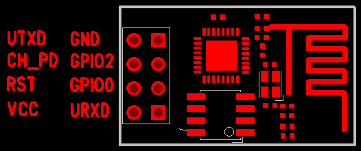
depending on the board, some pins need to be pulled high or low, to make it work. in case of my sample board pinout looks like this (top view):
my connection was as follows:
- Vcc to 3.3V
- GND to 0V
- CH_PD to Vcc
- RST to Vcc
- GPIO0 to Vcc
- GPIO15 to Vcc
- UTXD to RX on an attached serial port
- URXD to TX on an attached serial port
i was testing while connected to a USB-to-serial converter (any FT232-based board will do). just make sure it has I/O pins set to 3.3V!
last thing to know is the power consumption. my ESP8266 consumed 60mA after turning on. while doing “some I/O” it used 90mA. spec however says it power consumption can go up to 200mA or even 250mA in peeks. this is crucial observation is it eliminates powering ESP8266 from FT232's internal 3.3V stabilizer. in practice you need to have some external power source, like a batter (with a proper stabilizer) or laboratory power unit.
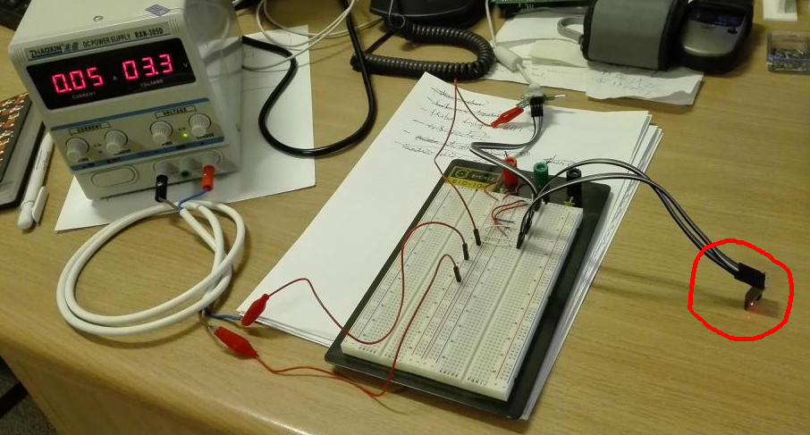
my final setup looked like this (ESP6288 has been circled in red):
if you are using quick development boards make sure connections are done right! i spend enormous amount of time trying to figure out where's the problem, because my GND cable, for FT232 was loose, while i was experimenting with different transmission speeds.
many ppl on the net complained about bad decoupling of the power line on these boards, so just to be on a safe side add one 10µF and one 100nF capacitors on the power line.
I/O: serial port
speaking about the serial port. please be noted that old firmware used 115200 bps for transmission, however since V0018902 it changed – 9600 bps is the new default!
ESP8266's I/O is text based, using AT commands set. make sure you are using CRLF (“\r\n” – hex: 0x0D 0x0A) lines ending - otherwise it will not work.
it is good to have a reference point here. if your connections are done right – it should work. i've wrote a short python script for testing communication:
#!/usr/bin/python
import sys
import time
import serial

# configure the serial connections (the parameters differs on the device you are connecting to)
ser = serial.Serial(port='/dev/ttyUSB0', baudrate=9600, timeout=0)
if not ser.isOpen():
    raise Expception("cannot open serial port - oops...")


def sendCmd(cmd):
    ser.write(cmd + "\r\n")

def readLine():
    line = ''
    while True:
        c = ser.read(1)
        if c == '\r':
            continue
        if c == '\n':
            return line
        line += c

def readResponse():
    buf = ''
    while True:
        line = readLine()
        buf += line + "\n"
        if line == 'OK' or line == 'ERROR':
            return buf

# hello world
print "sending request..."
sendCmd("AT+GMR")
sys.stdout.write( readResponse() )

# command loop
while True:
    sys.stdout.write("cmd>> ")
    cmd = sys.stdin.readline()
    sendCmd( cmd[:-1] )
    sys.stdout.write( readResponse() )
it tries to say hello to an attached module and then enters command-line mode, so that you can play around with the module a bit. script it is far from production quality and will not work for every command, but should be just enough to kickstart.
changing SW
normally this would be a pain in the neck. fortunately there is an excellent script for that, called esptool. using it you can query chip for parameters with a single command. it also allows you to change the SW. also making this tool work is probably the simplest way of checking if all the connections are good.
in order to enter SW change mode connect GPIO15 to GND and reset the device. once this is done, try running:
./esptool.py read_mac
if all the connections are fine, you should see MAC address of the connected module. if it works, you can flash it, using image obtained from the internet.
actual flashing is done with:
./esptool.py write_flash 0x00000 my_new_sw.bin
above will work for SW that comes as a single, binary image. some are however split into parts. read the manual to check under which addresses they should be stored.
final notes
ESP8266 is a nice and cheap piece of equipment. there are a lot of place it can come in handy. it is often referred to as a IoT-enabler. while it can be used in such manner, i'd be very careful about placing these devices everywhere. with its power consumption it can be expected to use >0.2W constantly (even if not transmitting) and up to almost 1W in peeks.
this means that battery-power solutions will require you to run around with fresh batteries daily.
as an alternative, you can plug it into a nearby power grid. this would however mean AC/DC converter (common mobile phone chargers + 5V to 3.3V converter), and loosing extra (say) 20%. while it is not a big problem for few devices, if you go towards IoT or sensor networks in a bigger scale, this extra power will be visible on your bill. it won't be a fortune, but will be clearly visible.
above notes do not refer to ESP8266 only. power consumption is a problem in WiFi networks. my point is that if you plan IoT, you might prefer to use a different technology, like: BTLE, ZigBee, Z-Wave, or… cables. in a lot of situations having small, thin cable in the wall is not a problem, and it can cut costs during exploitation. in such scenario, ESP2866 could be used as a hub for internal networking and/or a relay to the “regular WiFi”.
last option is to use it for devices that need to transmit rarely (say: once an hour). in such scenario, an external µC could do (and gather) measurements, enabling WiFi module just to transmit all the data at once, in a short burst, and then disabling WiFi module again. this way power consumption would be significantly lowered at the expense of latencies. although it is not an universal approach, it might be valid in some scenarios.

