Table of Contents
door light
it is quite often the on a staircase of a building i live in light is not on, when it should. first thing is that there is no window nearby. second thing is that, for some reason, light bulbs die too often in that place. in order to be able to easily locate keyhole on the door i've created a mini-project aiming at providing some extra light when it's dark. so i came up with a simple infrared (IR) proximity sensor, that when something moves near the sensor, it activates the light for about 42 seconds. not to scare off neighbors it is activated on a close proximity only – moving ones hand few centimeters from the sensor does the trick. :)
since version 2.0.0 whole electronics (including sensors) is located outside, and only powered from the inside (main fuses are on a power supply board). there is also simple option of activating it from the inside. dim-in and dim-out are also available on main light, not to flash user's eyes and to signal that timeout is approaching and device will turn lights off in a few seconds.
hardware
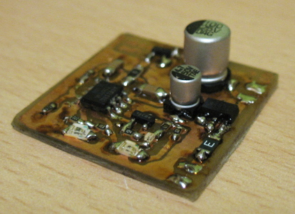
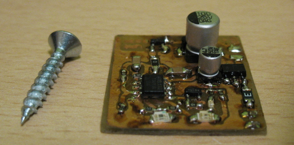
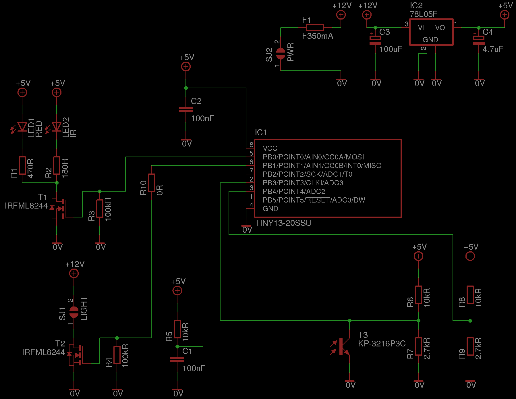
hardware part is supplied with +12V that is used to light up the LEDs, power IR sensors and is stabilized to +5V for uC. light from IR LED, when reflected, causes photo-transistor to change voltage on ADC3 pin of ATTiny13. the change is detected and LEDs are turned on for about 42 seconds. uC is clocked with internal RC oscillator, since no real precision is required here.
for users' convenience there is also an RED LED, that makes it easier to locate the sensor.
after applying power supply device lights. this is designed to be able to light up device from the inside, by simply disabling power for a short time. to make this usable, just put on-(off)1) on type switch on the power supply line.
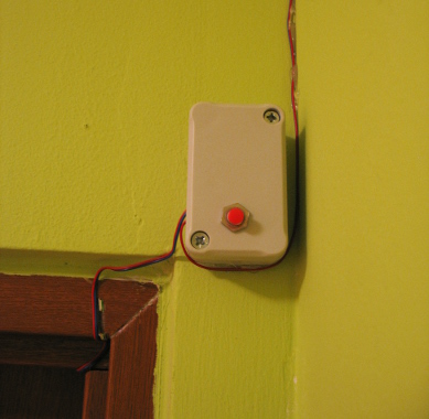
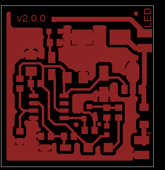
schema and PCB layout (yes - single layer!) are attached below.
power supply
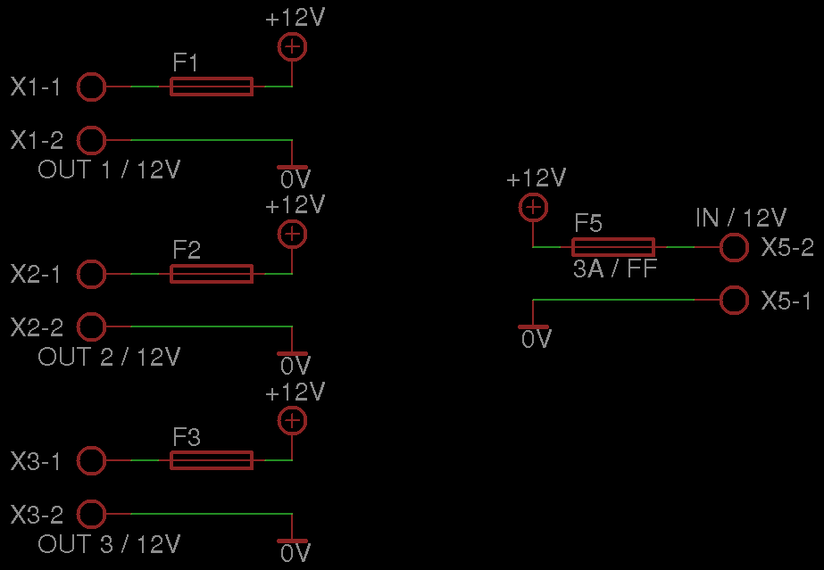
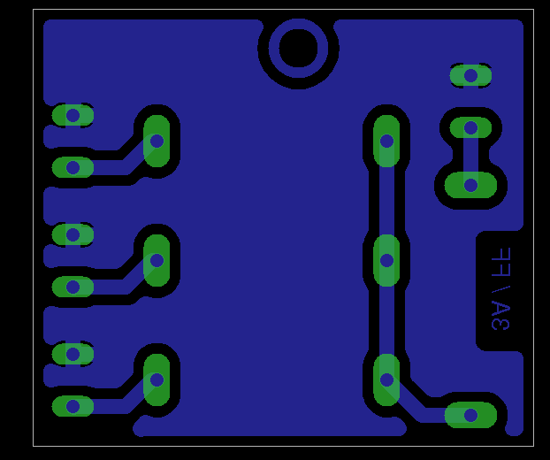
board does not have a fuse. it is important to add a protection though, since power is outside of your apartment and someone might short-circuit it, damaging the device. since the device also requires +12V power supply, both are assumed to be external. +12V power supply unit once can buy cheaply in every store. i've decided to go a step ahead and make splitter for the power as well, since i plan to connect more devices in the future, as well.
it is of course enough to provide supply directly to the door_light device - just remember to add a proper fuse.
software
source code is written in C++. whole program consists of a main loop that sleeps and reads ADC interchangeably. if the difference of readings between two iterations exceeds predefined threshold, LEDs are being turned off. each time threshold is reached again, timer for LEDs is reset, thus making it longer to be lit up.
downloads
full source code and the electronic schematic can be obtained from the github:
git clone https://github.com/el-bart/door_light.git

