Table of Contents
USB power controller
 this software-hardware solution allows you to turn on and off any devices connected to the computer via software. it has been developed in a free time to spare my plugging in and out devices manually. yes - i am lazy and proud of it. ;)
device has a wide number of usages. you can connect typical devices used with-or-near your computer and operate them, without have a need to have all of the cables on the desk. typical devices are:
- routers and switches (note: auto power up when computer starts)
- phone and laptop chargers
- printers (note: script may power it up when printer's queue is non-empty and shut down later on – fully automatic!)
- external hard drives
- monitors (note: can be connected with the screen saver)
- toasters, kettles, coffee machines… :)
- …
features
- 4 independent sockets to control
- USB standard device
- persistent memory for default states upon power on
- command line and GUI interfaces
- plain-text protocol used
- driver written in Python
- automatic power off devices when computer is shut down
hardware
hardware consists of two pain parts:
- the board, connected to the computer
- relays, turning on and off devices
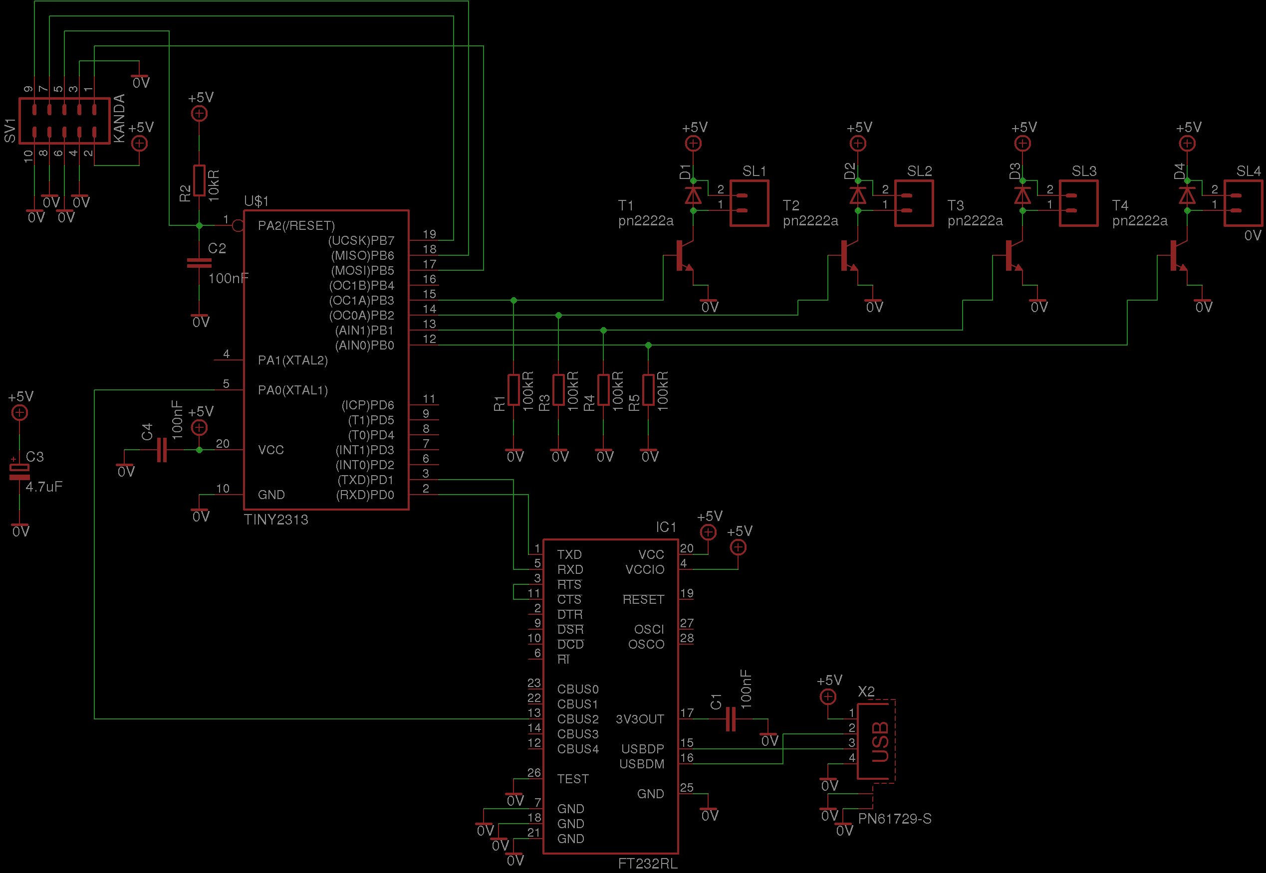
the board is quite simple. it consists of FT232 for USB communications, ATTiny2313 uC for doing all of the processing, communications and saving persistent state, transistors for controlling relays. see schematics (click on the image to enlarge it):
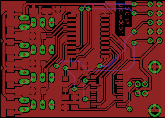
note that Kanda connector is optional. if you have an option to flash uC before soldering it, there is no need for you to use it at all. PCB view goes here (click to enlarge image):
note that board is almost one-sided. :) it is prepared so that you can make it as a one-side board at home and than wire the missing “bottom” elements together, with any isolated wire. if you do not use Kanda, only 3 wires are there. :)
as a base for the electric part i've decided to use Brennenstuhl's PremiumLine power extension cord, like this:
i choose it because of its modular design and on/off switches already available, which means that each socket is separated by design, thus making my hack simpler to apply. :) all you need to do is to make a hole for USB cable to fit and replace connectors to the switches with the relays of your choice and connecting relays to the control board, presented above. tiny wires are fine to connect relay control.
speaking of the relays. i've chosen RM84 relays, of polish production. they are controlled with 5V, 80mA. this fits perfectly, since 5V is the voltage we get from USB and 4*80mA=420mA + few mA for control electronics fits in 500mA USB 2.0 power limit as well.
software
software consists of two parts:
- computer driver
- device driver (i.e. uC code)
device driver
device driver is placed in board/src/ directory. to compile it it is enough to type:
make
by default release version is build. note that by default precompiled version is available in board/src/gen/release directory (bot binary and hex file).
to perform next steps you need to be root. in order to flash uC with build software type:
make PROFILE=release flash_mcu
now it is time to plug in USB cable and reprogram FT232, to serve its purpose:
make setup_ft232
this sets maximum current and output clock signal on the proper pins. this step has to be done only once.
computer driver
having device configured and flashed with software it is time to run the computer driver. driver script is written in Python and is placed under driver/ directory. following files are available:
- extension_cort_ctrl-gui.pyw – GUI interface version
- extension_cort_ctrl.py – command line version
- usbpwrctrl.py – module that implements device's communication protocol
module can be freely used from other scripts directly, though for simplicity, most of the time, command line tool should just do the trick. :)
download
latest version can be obtained via USB power control project on github. recent releases can be obtained via proper tags.


