Table of Contents
TIER
the TIER project was part of my master diploma work. TIER stands for “Tracked Impulse Electric Robot”1). to be precise it is a mobile robotic platform, that requests external controller (so it's not autonomous) – in this case PC.
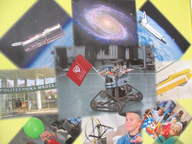
TIER has been also presented on DFN (Dolnośląski Festiwal Nauki) in city of Wroclaw on september 2007. some pictures from the described event can be seen on CJANT's home page.
the whole idea
the aim of project was to create mobile robot platform that can be controlled from PC-software level. robotic system was thought to contain basic AI to perform its main task: move around avoiding obstacles. yes – this means that robot controlls itself and user has no influence on its decisions, except for trying to cross its way (aka: become terrain obstacle).
as the input sensor monocular camera has been used. although this far from being the best choice for given task, the project was more scientific then production-oriented. i just wanted to work with simple (but real!) vision system.
development
in this section i'll show some pieces of information i've saved while developing mechanical construction, electronic parts and software. they'll be presented shortly in following sections. for more detail refer to my master thesis.
mechanical construction
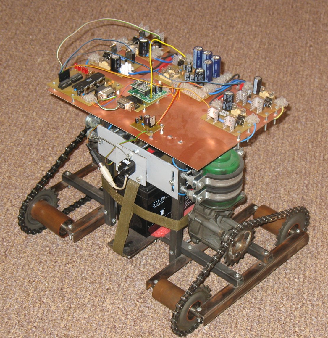
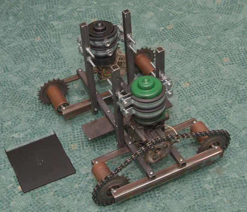
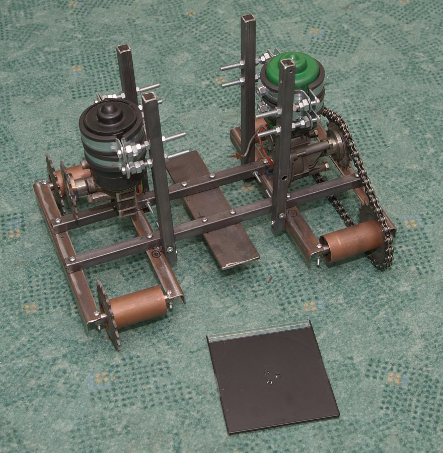
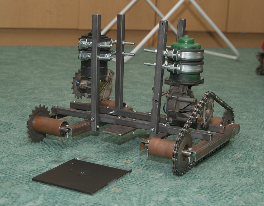
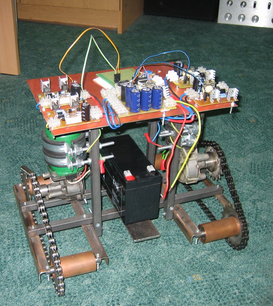
the main “real-world” part was the mechanical construction. it's all made of metal parts connected together with screws. engines used are actually Volkswagen's wipers motors, each of them about 25W of electric power. tracks and sprockets were bought in a bike shop. power source is single, 12V gel battery for motor (about 9Ah capacity).
some pictures shows all of these bellow (CD-box is used as size-reference):
electronic parts
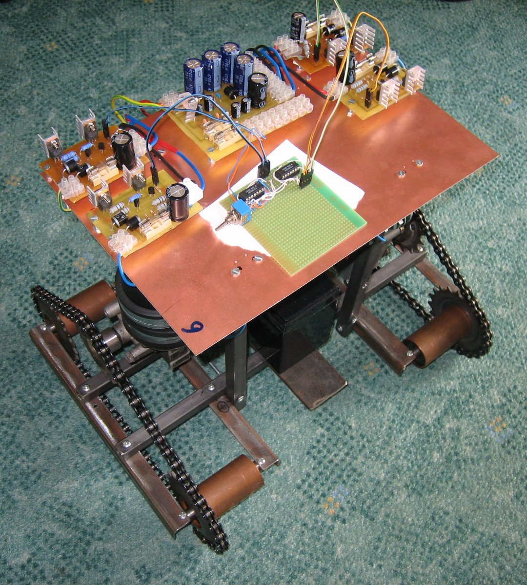
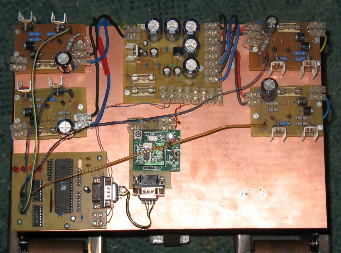
the only bought circuit was transciever. all the others PCBs were prepared using Eagle.
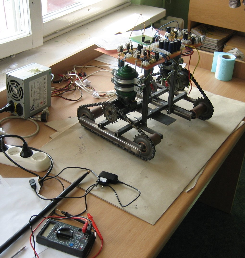
here are some pictures from time i have been working on electronics:
whole electronics and microcontroller's software can be found along with the software, in the download section.
PC-software overview
software on PC side was mainly for image processing and some basic controll over physical robot. it assumed that data might be read from other computer and send over network. to capture data Video Capture Server (VCSrv) application was used. later on data were send to Video Capture Client (VCCln) and processed using Graphics and CGraphics libraries (second one was C++ wrapper for C code for image manipulation i've wrote many years ago, during my studies). after raster processing vector image of chosen edges is created and is passed to decision-making algorithm (placed in Zuchter application) that sends simple orders (like: “turn right”) to robot using custom Communication Protocol (CommProto).
how does it work
at this moment i'll present only a very basic idea about it. the more detailed description of system as whole can be found in my master thesis.
there are 2 important steps:
- computing obstacle-floor edges.
- computing distance of them from the robot (depth).
marking edges
this is 3-step algorithm:
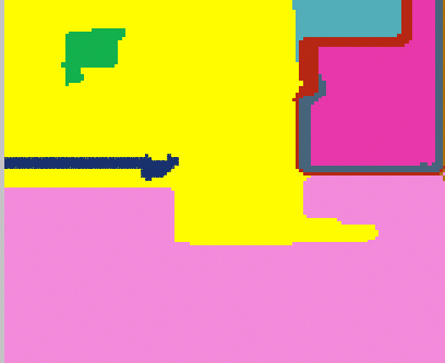
- image is segmented.
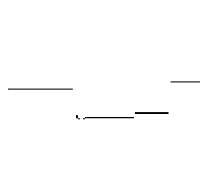
- edges between segments are chosen so that they are the closes ones looking from robot (with our assumptions this means: the one that are the lowest on the image).
- vectorise edges image.
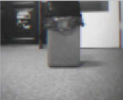
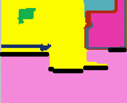
segmentation example can be seen on following image of trash can:
obstacle-floor edges image and the same image placed on original one:
depth from monocular image
the main clue on how to read depth from monocular image simple but a bit tricky – you need to do some assumptions. in my case these were:
- all of obstacles are horizontal and flat (not sticking-out parts).
- all obstacles lie on a floor.
- floor is flat.
- floor and obstacle must differ in colour (at least slightly)
to make things even simpler i've decided to place camera horizontally to the floor (i.e: it points directly ahead of robot). knowing this, you can compute how far the object is by knowing how “high” it is on your input image + knowing some constants.
for distance ahead from robot it is illustrated here:
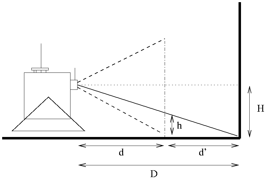
from above we have: H/(d+d')=h/d' → d'=dh/(H-h).
for distance on side of main optical line we do similar computations, but this time we need to include already computed “depth ahead”:
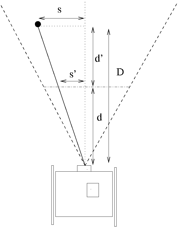
and so we have: S/D=s'/d → S=D/d*s'
example runs
you can download example movie of TIER's short run (watch online) in my room. this is the only one that comes with sound the robot makes while moving around.
there is also an example of long run (watch online) available. this shows about 2 minutes of robot moving around the room, avoiding obstacles.
on image processing stages (watch online) record you can see 4 different windows on the screen. this is how robot sees the environment. these are:
| window position | processing stage |
|---|---|
| lower-right | input image from the camera |
| upper-right | segmentated input image – all basic components are marked with one color |
| lower-left | the obstacle-floor edges mark |
| upper-left | deepth map computer from marked edges |
download
latest versions can be downloaded via TIER project on github. recent releases can be obtained via tags.
all of the software and hardware is released under the revised BSD license. the only exception is most of the code placed under software/CGraphics/segment directory. this code is external and is used with permission of its author, who holds all rights to the original. note that this code has been slightly optimized and fixed, so that it could be used within constantly-working system.
TIER at DFN
this year (2008) once again TIER has been presented on DFN as a part of AI lectures.
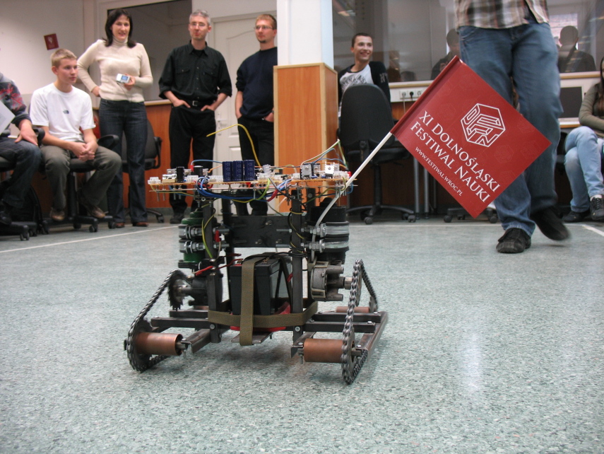
in 2009, once again TIER has been show as a part of (this time) XII DFN. pictures from last year have been shown on DFN's posters as well. :) read more on my blog.
