2013.12.16 - ADC and Vcc
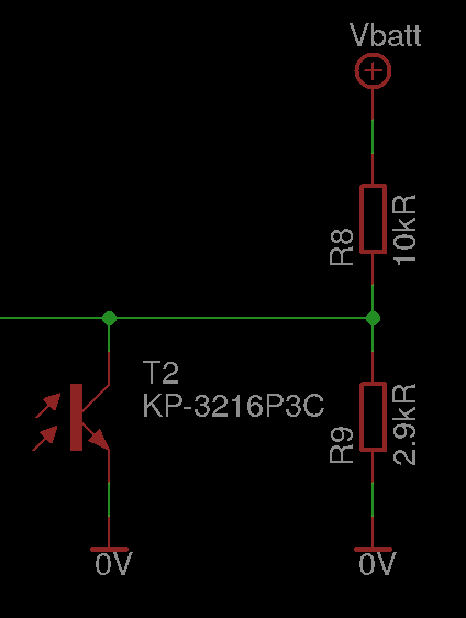
recently i've created a new version of door light project (v3.0.0-rc2, to be precise). it now includes 3.3-5V version, with DC/DC step-up converter for main LED supply, so one can power it from 3 AAA batteries. while working on new version, i've used 12V version as a base. it used 12V for main power supply and stabilized it to 5V for µC power supply. the main part – a photo-transistor for light change detection – used a simple schematic, based on voltage divider like this:
when more photons were captured by the transistor, voltage on the divider dropped. photo-transistor’s collector was connected to µC's ADC and so the voltage was checked by the software, filtered, and decision to lit up was made. worked like a charm for 12V version. but the battery based didn't do well. the main difference was that now LED powering was done via DC/DC and the battery was connected directly (i.e. w/o stabilizer) to the µC. effect? when DC/DC started and lights were turning on (slowly, with PWM), after about 200ms it turned off and start again. the funny thing was that µC itself worked fine (no reset). what was wrong then? after using oscilloscope to do Vcc monitoring it appeared that while LEDs are lit up, voltage slowly drops. this in turn caused total voltage drop on the divider and so on the collector of the transistor, even though lighting conditions were not changed. this caused µC to think it should lit up again, and so on in the loop. grace-time for starting do not solve the issue, since the very same issue appears when dimming lights out prior to turning it off.
i had one ace in my pocket – i had the same divider, but w/o photo-transistor, connected to another pin, for Vcc monitoring. i though about just storing difference between photo-transistors' voltage and Vcc, to mitigate the differences. unfortunately the change was too fast and it did not worked out. fix needed to be done in the hardware. i could simply add stabilizer, but this would cause extra power losses, and since we're running on battery, this was not a good design choice.
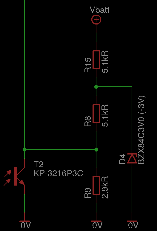
the solution was to change divider slightly, to ensure it has common “base point” for measurements, regardless of fluctuating Vcc level:
by doing so, i've ensured that both zener's current is small and measured voltage is (roughly) independent on Vcc fluctuations. since µC usese internal 1.1V reference voltage, this sole change was enough to make it right.


