Table of Contents
Universal Stepper Motor Controller
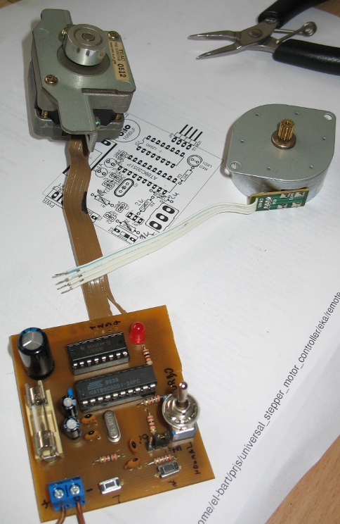
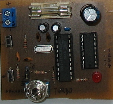 some time ago my dad asked me to help him with controlling capacity of capacitor located on the roof. capacitor is to be used for fine-tuning amateur radio's (ham radio) antenna that he uses. the key was to do it remotely, so that changing frequency would not require visiting the roof each time.
what we've worked out is to use variable capacitor, rotated with stepper motor remotely. and so, the first step is to design and build stepper motor controller.
whole USMC project is released under Revised BSD license, i.e. do what ever you want with it. :)
electronics
there are 2 buttons to indicate left/right direction, turbo-switch that changes from step-by-step work to continues rotation (to move through wide ranges faster) and unipolar/bipolar jumper. signals are handled by AT89C2051 uC (from 8051 uC family) that generates proper signal sequences for L293D stepper motor driver.
logical schema (click to enlarge):
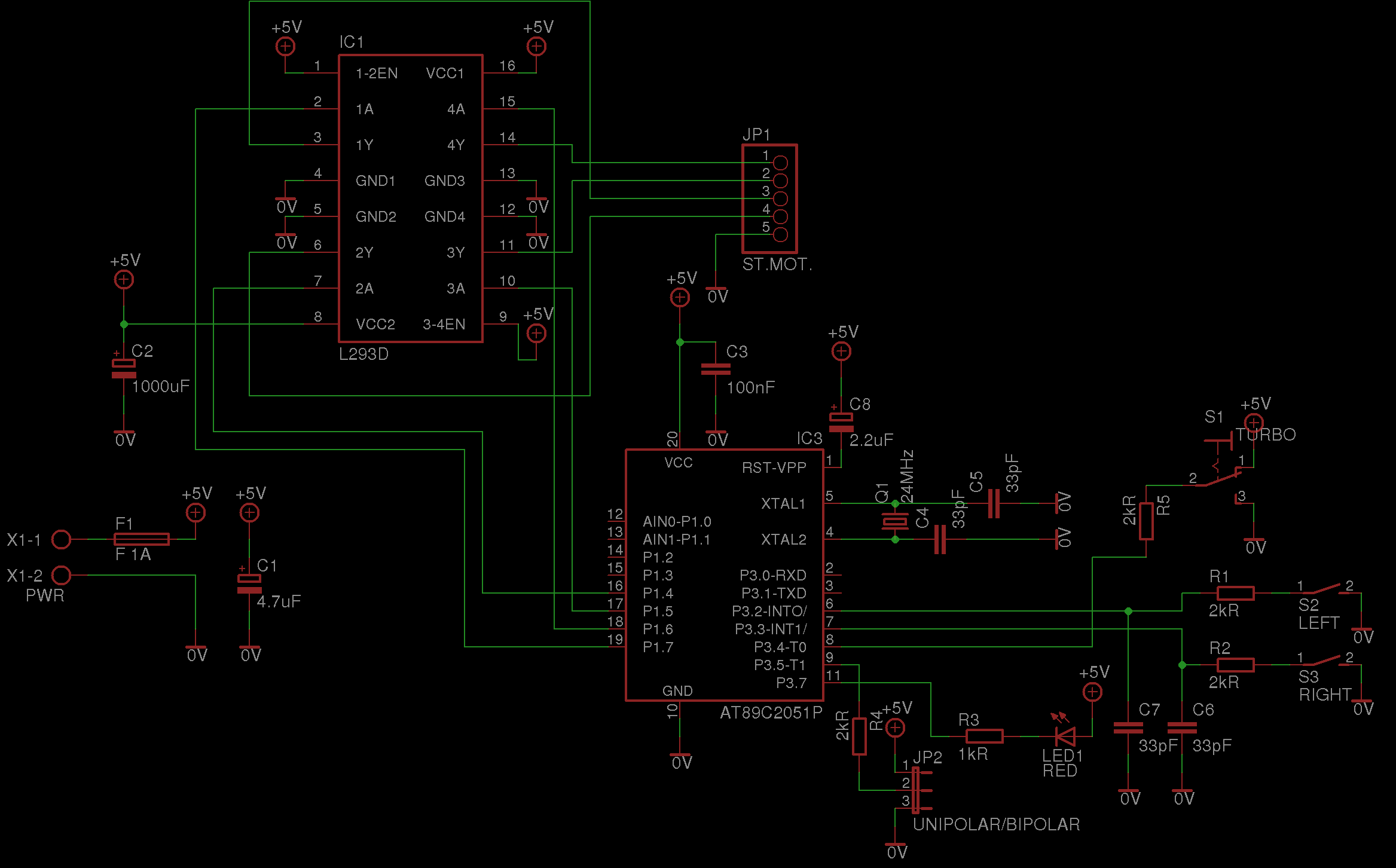
notice that it is VERY important to use L293D, not “raw” L293, since first one has internal diodes protecting lines from engine coils reverse induction voltage. to minimize number of elements in the circuit there are no diodes in discrete form, but L293D is a must!
board schematic (click to enlarge):
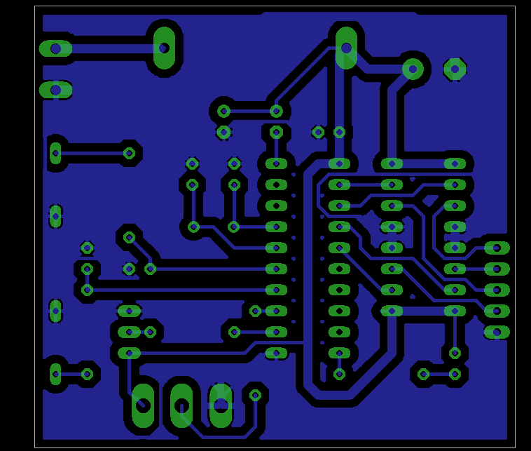
PCB elements' names view (click to enlarge):
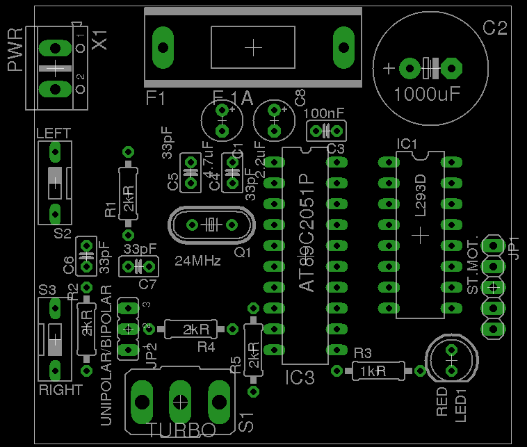
board, as designed, uses 24MHz oscillator. why? i just had plenty of them so i've used one. since code is not complicated and does not required high CPU power i'd expect it to work fine even with 1MHz oscillator, assuming delay_ms() function will be updated to new timings. feel free to experiment. if you'll use different parameters, please let me know. :)
software
to control the device software in C has been prepared. SDCC toolchain has been used to compile and link the code. in the download package proper makefiles are prepared so that simple 'make' will generate binary and intel hex output files.
code is decomposed into several modules, to make it easier to read and understand:
- usmc.c – main program loop
- delay.c – call to generate delays in code
- idle.c – support for idle mode
- init.c – initialization procedures
- interrupts.h – interruption procedures handles (used in usmc.c only!)
- motor.c – stepper motors (bipolar and unipolar) driver
- uC.h – some uC-specific settings and includes, kept in one place
software uses uC's idle mode when nothing is happening to keep power consumption as low as possible.
to indicate that engine is moving LED is blinking shortly for each step made.
to flash uC you can use linux tool EZDlin… or anything you want. :)
though code is written in C, there is one inline assembler piece of code, that generates time delay (delay.c). when you'd like to change oscillator you must remember to update this call as well.
download
further improvements
what more can be done:
- add support for RS232 (or USB) communication with the computer.
- choose components so that it will be able to work in outdoor conditions (say: -40 to +100 degrees C).
- update delay_ms() call from delay.c so that it will be easier to change oscillator in use.
- use persistent memory (EEPROM?) to save last position it was on when next power-on comes.
